GT50 Update: 99.5% Complete and Ready for Assembly
Over the past several months, Hill’s manufacturing team has developed 438 high-complexity, precision gas turbine prototype parts from raw materials and first principles. Those parts have required 71,668 individual machining and production operations, of which 99.5% are now complete. The remaining finishing touches are being applied to the last twenty components.
Within a week, the very first GT50 prototype will be assembled, and shortly after, the fires will be lit.
18 May 2026
Rotor Dynamics: Balance, Repeatability, and Precision
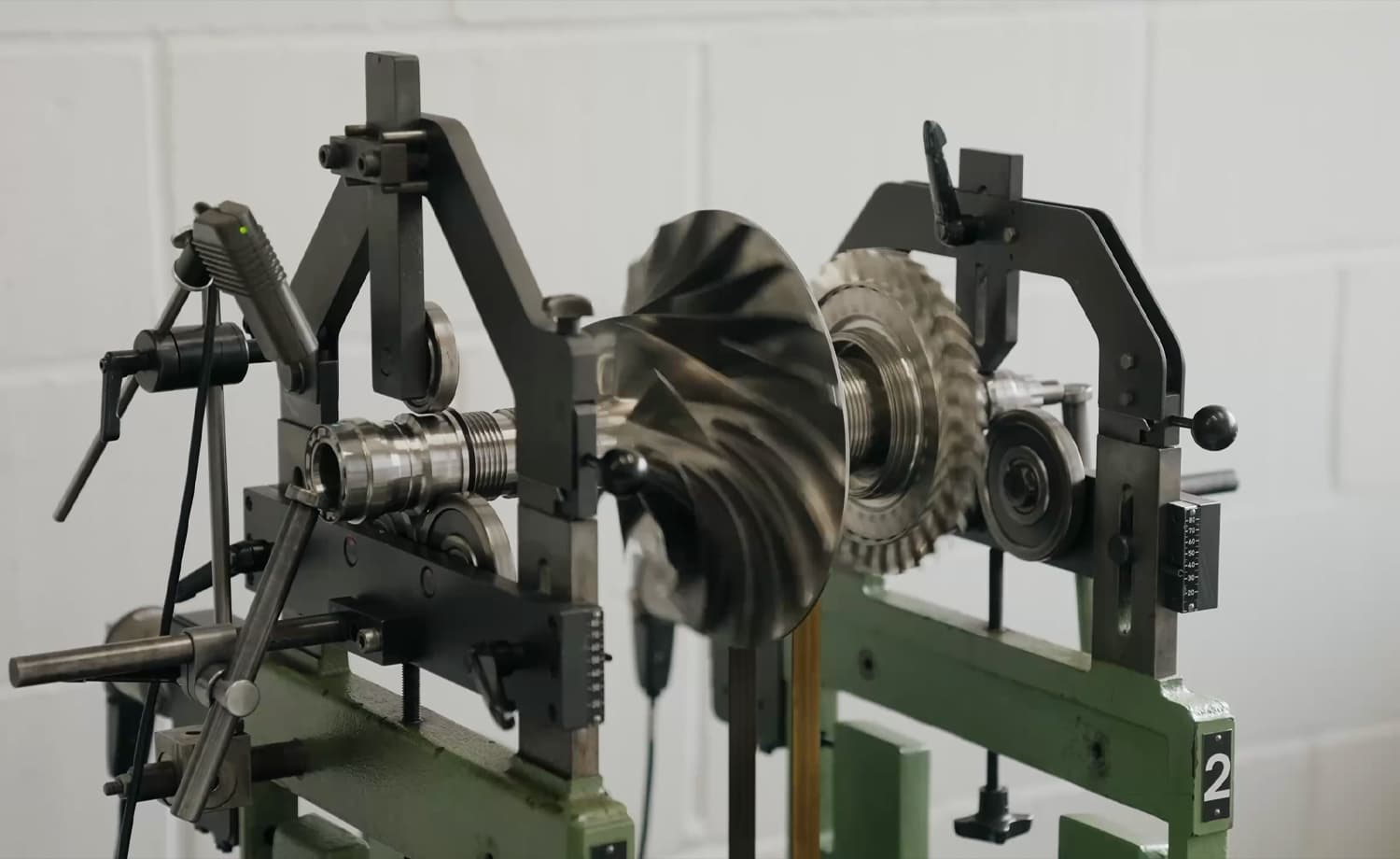
The gas generator rotor of the GT50 spins at approximately 50,000 RPM. At those speeds, even microscopic imbalances generate destructive forces. In the previous update, Hill detailed the painstaking process of balancing the rotating assembly. That milestone has now been validated: the rotor balances cleanly on the machine, and it reproduces the same balance point after disassembly and reassembly.
This repeatability is vital because the rotor must be partially disassembled to fit inside the engine casing during final build. The team has invested significant effort in making that transfer process robust, eliminating any risk of rotor-dynamic surprises during the first run.
The "Tuning Fork" Solution
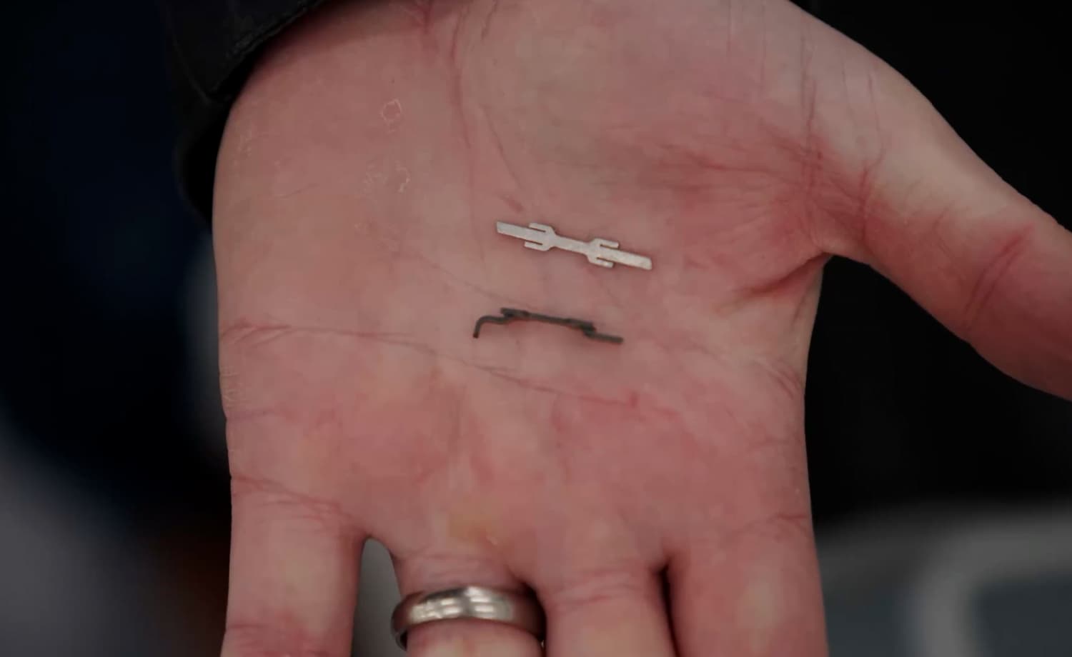
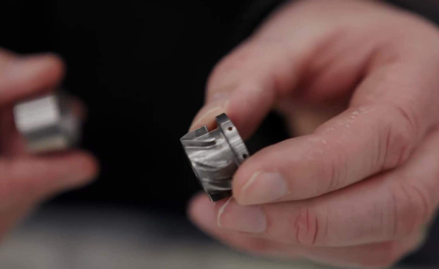
Turbine blades on the GT50 are retained in the disc by a fir-tree root, which handles the immense centrifugal load at 50,000 RPM. Axially, however, the blades are secured by small pressed-metal clips that are bent over to lock them in place. The original design, a simple "rooftop" shape, proved difficult to hold within tolerance. When the rotor was assembled, blade-to-blade variation in axial freedom became apparent.
The fix is a redesigned clip that resembles a tuning fork. Manufactured by laser cutting, stamping, or wire erosion, its flat tangs locate accurately in the groove at the base of each blade. A custom press tool forms the curved profile so the clip sits snugly underneath. The result: blades are now completely secure in the latest production disc, with negligible axial variation and no compromise to the balance routine.
To protect the disc and blade root from scratching, the tuning-fork tips are deburred in a rumbling machine. Under magnification, the microscopic fillet radiuses are visible, just enough to eliminate sharp corners without altering the bulk geometry.
Curvic Couplings and Manufacturing Sequence
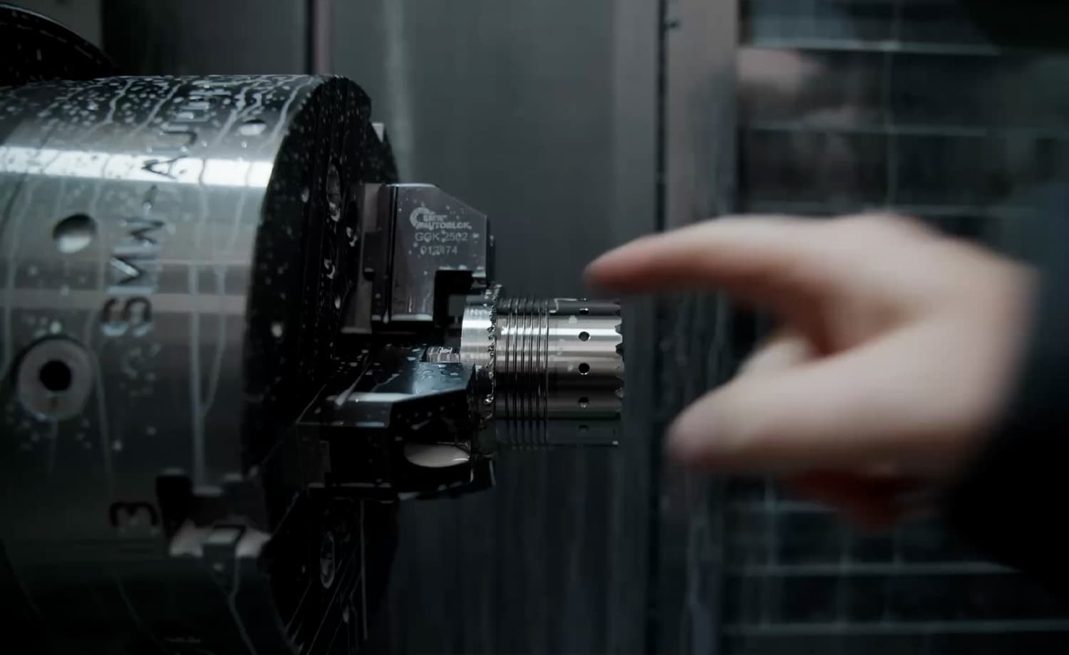
Even a seemingly minor change can cascade through a precision manufacturing chain. A few weeks ago, slotted holes in one rotor component were replaced with round holes to improve manufacturability. The change worked, but it altered the order of subsequent operations, and threw the Curvic couplings out of tolerance.
A new component has been produced with an updated processing order to keep the front and rear Curvic geometry within the sub-micron tolerances required. The final machining is now underway on the component destined for the test engine.
Bearings, Races, and Rolling Elements
High-speed bearings are among the most unforgiving components in any gas turbine. Hill’s team has now completed the critical elements of the gas-generator bearing system:
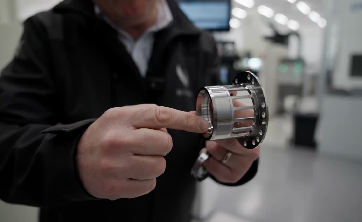
- Outer race with spring bar: This acts as the suspension system that attaches the bearing to the engine structure and controls stiffness for rotor-dynamic management.
- Inner race: Handles a significant share of axial load and provides the sealing surface for the squeeze-film damper that damps rotor vibrations.
- Cages, rollers, and precision balls: Maintain exact ball and roller positions at close to 50,000 RPM.
The outer raceway is held to sub-micron roundness and cylindricity - one-thousandth of a millimetre. Every one of these components is machined from a specific steel formulated to retain strength and hardness through the searing temperatures at the core of the engine.
Major Structural Casings Take Shape
With the rotating machinery nearing completion, the static architecture of the engine is also arriving in finished form:
- Inlet casing / accessory gearbox rear face: The forward structural backbone of the engine, including the bell-mouth air intake and the bosses that carry gears and bearings.
- Accessory gearbox front cover: Provides the second half of the bearing mounts and machined faces for the starter-generator, oil pump, fuel pump, and heat exchangers.
- Combustor casing: The fully instrumented, metal 3D-printed prototype has had its front and rear flanges machined, together with internal details for seals and high-temperature components. Final 5-axis operations remain to dress injector mounts and instrumentation flanges.
- Interduct: The gas-path diffuser sitting between the gas-generator turbine exit and the power turbine inlet. Also 3D-printed in superalloy and finish-machined to accept instrumentation bosses.
Combustion Liner and Fuel System
The first GT50 annular combustion liner is complete. It carries the combustor head with floating springs to seal fuel injectors and swirlers, together with film-cooling and dilution holes already implemented. The only remaining operation is the placement of the final dilution holes, pending ongoing combustion-rig testing to confirm the optimal igniter-plug position.
The fuel-delivery train is equally refined. Cast in-house at PC1, the fuel manifolds are machined to create internal passageways that route fuel to each nozzle. The nozzles themselves screw into the manifolds and are surrounded by swirlers that atomise fuel and establish the standing recirculation zone essential for stable combustion. A full range of spray nozzles has been prepared so the combustion system can be tuned precisely on the final test rig before the selected configuration is frozen for the first prototype engine.
Turbine Blades and Blade Liner Rings
All manufacturing on the turbine blades is now finished. The blades destined for the first engine are undergoing final dimensional checks and CT scanning to verify that any internal defects remain within acceptable tolerances. Meanwhile, the blade liner ring, the casing within which the turbine disc and blades rotate, has had its abradable coating machined back to provide the tight tip clearances required for efficiency, plus a safety margin against high-power rubs during development.
Instrumentation: The Longest Lead Item
One of the most time-consuming aspects of any prototype engine programme is instrumentation. To capture pressures, temperatures, and flow velocities across the gas path, the team has designed and manufactured rake and bracketry systems that protrude into the annulus at multiple stations. Hypodermic tubing runs the length of the engine to carry those measurements to sensors mounted where they can survive the thermal environment. The sensors themselves are in stores, awaiting fitment.
Test Rigs: From Rufus 1 to Rufus 3
While the engine components converge on PC1, the fuel and combustion test programme has advanced in parallel.
- Rufus 1 - the single-channel rig - has proven nozzle behaviour, ignition stability, and early control algorithms.
- Rufus 3 - a new three-channel rig representing one quarter of the annular combustor, is now being assembled. It will verify cross-lighting stability between injector streams, optimise igniter positioning, and confirm the fuel schedules and airflow parameters that the FADEC will use during the first engine runs.
The straightened combustion liner for Rufus 3 is currently being fitted into its housing, with testing expected to begin within days.
The GT50 Test Cell
The test cell itself is a repurposed shipping container, acoustically lined to contain the noise of prolonged gas-generator testing without disturbing the surroundings. Inside, the test bench—originally built for speed-reduction-gearbox validation—is being extended to accept the gas generator, then the power turbine, and finally the complete lubrication and off-engine services required for early running.
For later power-turbine tests, a concrete containment structure will be added around the container to protect against the unlikely event of a disc burst. Anti-vibration mounts, electrical services, and full instrumentation infrastructure are already installed.
The Countdown
Many said Hill faced a mountain in choosing to design and build its own gas turbine for the HX50. The mountain has been climbed one machining operation at a time. With 99.5% of all production operations complete, the path is now clear:
- Final finishing touches on the last twenty parts.
- First GT50 prototype assembly in approximately ten days.
- Engine light-off and testing—the first helicopter engine built in the United Kingdom in nearly fifty years.
The fun, as Jason Hill puts it, is about to start.


JOIN OUR GROUP PRESENTATION
Are you interested in the HX50? Book your spot in our group presentation and learn why the HX50 will be better than your current helicopter.
What's in the presentation
Who
Mischa Gelb (aka Pilot Yellow) and Ruben Dias
What
Exclusive full details about the HX50 not yet available to the public
How
30-minute presentation + Q&A
Be part of the journey
Get all the relevant news and updates about the HX50 delivered to your inbox.
HX50
Exterior Concept
Interior Concept
GT50 Turbine Engine
General Aviation 2.0
Hill Digital Cockpit
News & Stories
Technical Details
Range Simulator
Journey to HX50
ADDRESS
Hill Helicopters
Unit 3, Shackleton Way
Stafford, ST16 1GY
United Kingdom
Contact
General Enquiries:
+44 (0) 1384 590700
Accounts:
+44 (0) 1384 590700
Sales:
+44 (0) 1889 228040
hello@hillhelicopters.com
ADDRESS
Hill Helicopters
Unit 3, Shackleton Way
Stafford, ST16 1GY
United Kingdom
© 2026 HILL HELICOPTERS